Common-emitter amplifiers give the amplifier an inverted output and can have a very high gain and can vary widely from one transistor to the next. The gain is a strong function of both temperature and bias current, and so the actual gain is somewhat unpredictable. Stability is another problem associated with such high gain circuits due to any unintentional positive feedback that may be present. Other problems associated with the circuit are the low input dynamic range imposed by the small-signal limit; there is high distortion if this limit is exceeded and the transistor ceases to behave like its small-signal model. One common way of alleviating these issues is with the use of negative feedback, which is usually implemented with emitter degeneration. Emitter degeneration refers to the addition of a small resistor (or any impedance)[disambiguation needed] between the emitter and the common signal source (e.g., the ground reference or a power supply rail). This impedance RE reduces the overall transconductance Gm = gm of the circuit by a factor of gmRE + 1, which makes the voltage gain
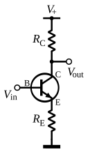
 Figure 2: Adding an emitter resistor decreases gain, but increases linearity and stability
So the voltage gain depends almost exclusively on the ratio of the resistors RC / RE rather than the transistor's intrinsic and unpredictable characteristics. The distortion and stability characteristics of the circuit are thus improved at the expense of a reduction in gain.

Characteristics
At low frequencies and using a simplified hybrid-pi model, the following small-signal characteristics can be derived.
If the emitter degeneration resistor is not present,  . As expected, when
  is increased, the input impedance is increased and the voltage gain
  is reduced.
 appears like a larger parasitic capacitor
  (where is negative) from the base to ground[1]. This large capacitor greatly decreases the bandwidth of the amplifier as it makes the time constant of the parasitic input RC filter
  where
where  is the output impedance of the signal source connected to the ideal base.
The problem can be mitigated in several ways, including:
Rooselvet Ramirez EES
At low frequencies and using a simplified hybrid-pi model, the following small-signal characteristics can be derived.
| Definition | Expression | |
|---|---|---|
| Current gain |  |  |
| Voltage gain |  | 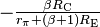 |
| Input impedance |  | 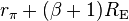 |
| Output impedance |  |  |
. As expected, when is increased, the input impedance is increased and the voltage gain is reduced.[edit] Bandwidth
The bandwidth of the common-emitter amplifier tends to be low due to high capacitance resulting from the Miller effect. The parasitic base-collector capacitance appears like a larger parasitic capacitor (where is negative) from the base to ground[1]. This large capacitor greatly decreases the bandwidth of the amplifier as it makes the time constant of the parasitic input RC filter where is the output impedance of the signal source connected to the ideal base.The problem can be mitigated in several ways, including:
- Reduction of the voltage gain magnitude
 (e.g., by using emitter degeneration).
 - Reduction of the output impedance of the signal source connected to the base (e.g., by using an emitter follower or some other voltage follower).
- Using a cascode configuration, which inserts a low input impedance current buffer (e.g. a common base amplifier) between the transistor's collector and the load. This configuration holds the transistor's collector voltage roughly constant, thus making the base to collector gain zero and hence (ideally) removing the Miller effect.
- Using a differential amplifier topology like an emitter follower driving a grounded-base amplifier; as long as the emitter follower is truly a common-collector amplifier, the Miller effect is removed.
Rooselvet Ramirez EES
No hay comentarios:
Publicar un comentario